Total: $4,848.00
On Sale!


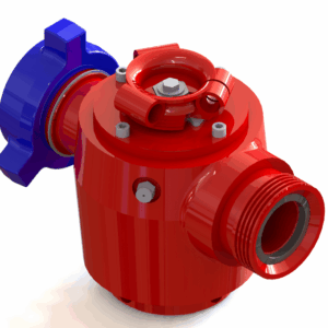
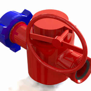
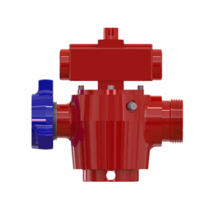
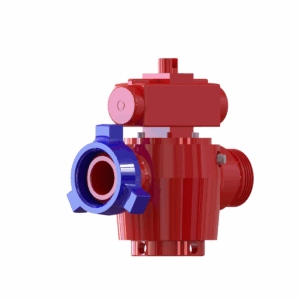
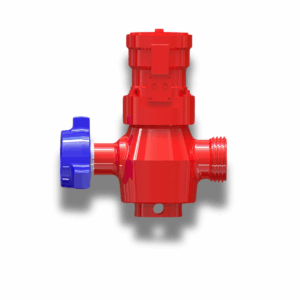
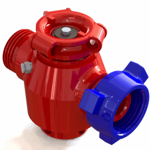
When the stakes are high in oil and gas, you need equipment you can trust. Our 2″ FIG. 1502 – 9 Valves, 2 Choke Manifold is engineered for the most demanding high-pressure oilfield environments. This robust system provides the precision and safety you need for critical operations like drilling, well testing, and workovers. Built to the highest standards, it’s your go-to solution for reliable wellbore pressure management.
1 in stock
Delivery and return
Delivery and return
For Return/Refund Please see here.
SECTION 1 – ORDER PROCESSING TIMES
Orders typically take 1 – 2 business days to process before the order is released to the warehouse. This excludes weekends, holidays, and all other non-working days. Orders placed after 13:00 CST will be processed the next business day.
If immediate order and pickup is required, please call us at
(405) 666-5011 to speak with a technical sales representative or e-mail at [email protected]
Due to rapidly fluctuating inventory levels, some items from your order may be partially or completely out of stock. Upon receipt of your order, we will notify you of any stock shortages and advise the lead time for the out of stock items. Typically, the manufacturing lead times will be less than 1 week for common products and 1-2 weeks for limited stock uncommon products.
SECTION 2 – LOCAL PICK-UP
Local pickup is available Monday – Friday during regular business hours. An email will be sent when your order is ready for pick up and will include the contact detail for the local warehouse. You must call in advance to schedule a time for pickup as most products require handling equipment to load.
After hours pickup can be scheduled in advance if required, please call or email to make arrangements.
Please note that due to the vast number of products offered, your chosen pick up location may not have enough stock at the time of order. Upon receipt of your order, we will notify you of any stock shortages for the local warehouse and advise the lead time for the back ordered items. Typically, the lead times will be less than 1 week if the products are in stock at other locations.
Pickups will be scheduled once all products are in stock at the local warehouse. However, split order pickups can be arranged upon request.
Local pickup is available at the following locations:Houston
Houston - 27381 Midline Rd, Cleveland, TX 77327
Oklahoma - 512 N Morgan Rd, Oklahoma City, OK 73127
North Dakota - 2000 50th St W #4, Williston, ND 58801
Odessa - 12511 W. Interstate 20, Odessa, TX 79766
Dubai, U.A.E. - Street no. N506, Ware house Unit#WT01-FB06|Jebel Ali Freezone (North JAFZA) Dubai
Shipping Information
Shipping Information
SECTION 3 – LOCAL DELIVERY
Local delivery is available Monday – Friday during regular business hours.
An email will be sent when your order is processed with a date and time for the delivery. You must ensure safe access for the delivery and all required equipment and personnel are available as most products require handling equipment to unload.
After hours delivery can be scheduled in advance if required, please call or email to make arrangements.
Please note that due to the vast number of products offered, your local warehouse may not have enough stock at the time of order. Upon receipt of your order, we will notify you of any stock shortages for the local warehouse and advise the lead time for the back ordered items. Typically, the lead times will be less than 1 week if the products are in stock at other locations.
Deliveries will be sent once all products are in stock at the local warehouse. However, split deliveries can be arranged upon request.
SECTION 4 – SHIPPING COLLECT / CUSTOMER ACCOUNT
In most cases, we can ship collect, you may arrange your own carrier/pickup or have us ship using your established carrier account.
SECTION 5 – DOMESTIC SHIPPING
After placing your order, we'll find the optimal shipping solution for you, balancing speed and cost. You'll be notified of the final shipping charges via email, Post your confirmation Order Will be Shipped.
SECTION 6 – INTERNATIONAL SHIPPING
After placing your order, we'll find the optimal shipping solution for you, balancing speed and cost. You'll be notified of the final shipping charges via email, Post your confirmation Order Will be Shipped.
SECTION 7 – PACKAGING
- Manufacturers standard packaging and palletizing included
- Special requirements for export packaging, crating, bracing, preservation, etc. are NOT included. Please contact us with any special packaging requirements.
- Assemblies which are meant to be dismantled shall be dismantled into the smallest sizes to optimize freight costs and time.
SECTION 8 – SHIPPING EXCEPTIONS AND CLARIFICATIONS
- Over dimensional and/or overweight packages are not included in the shipping rate schedules
- Import fees, taxes and tariffs and any other import or taxes costs are the responsibility of the customer unless otherwise agreed to in writing.
- No guarantees for shipping, delivery times, processing times are implied or warranted.
- Some areas, regions or countries may not be eligible to place orders due to trade restrictions, embargos or other governmental restrictions.
- We will do our best to manage the shipping costs within our stated rate schedule, however, some orders due to their composition and destination may require special handling. In these cases, one of our team will contact you do discuss shipping solutions.
Composition and care
Composition and care
Composition & Care for Oilfield Equipment
Our oilfield equipment is manufactured from high-quality, forged, and heat-treated alloy steel, ensuring exceptional durability, corrosion resistance, and performance under extreme conditions. Each component is precision-engineered to meet or exceed API 6A standards, guaranteeing safety, reliability, and long service life in demanding oilfield operations.Care & Maintenance:
- Use Only Specified Seals & Components – Always use recommended gaskets, seals, and replacement parts for optimal performance and leak prevention.
- Regular Inspection – Check for wear, corrosion, and pressure integrity to ensure continued safety and efficiency.
- Proper Handling & Storage – Store in a clean, dry environment, and avoid exposure to extreme weather when not in use.
- Routine Lubrication – Apply approved lubricants to threaded and moving parts to prevent friction damage and ensure smooth operation.
- Follow Manufacturer’s Guidelines – Adhere to recommended pressure ratings and installation procedures to avoid equipment failure.
- For best performance and safety, always use genuine products and expert-recommended accessories supplied by Blaze Sales & Service.
Description
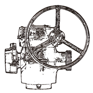
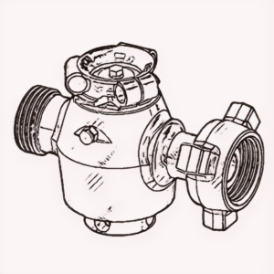
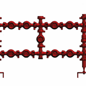
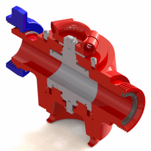
2″ FIG. 1502 – 9 Valves, 2 Choke Manifold
In the demanding world of oil and gas exploration and production, control over wellbore pressure is not merely a preference, but an absolute necessity. The 2″ FIG. 1502 – 9 Valves, 2 Choke Manifold, offered by Blaze Sales and Service, stands as a testament to uncompromising engineering and reliability. This robust and meticulously designed system is your frontline defense and precision tool for managing the formidable forces encountered in high-pressure oilfield environments. Built to the stringent FIG. 1502 standard, it ensures a secure, leak-proof connection capable of withstanding extreme pressures, making it indispensable for drilling, well testing, and workover operations. With its array of nine strategically placed valves and a dual-choke configuration, this manifold provides unparalleled flexibility and safety, allowing operators to precisely control flow rates and pressures, thereby safeguarding personnel, equipment, and the environment. Invest in the integrity of your operations with equipment engineered for resilience and supreme performance.
CONSTRUCTION:
* 2″Fig. 1502 choke manifold Assembly.
* Consists of two numbers of choke and nine numbers of plug valve.
* Provision for measurement of pressure and temperature.
* Available with skid.
* Approximate weight is 604.5 kg.
Features:
- FIG. 1502 Compliance: Designed and manufactured to meet the rigorous FIG. 1502 pressure rating, ensuring high-pressure integrity and reliability in the most challenging oilfield conditions.
- Nine Valve Configuration: Equipped with nine high-quality valves, offering extensive control over flow paths, enabling bypass, isolation, and intricate pressure management.
- Dual Choke System: Features two choke lines (one main, one bypass/kill line), providing redundant pressure control, allowing for continuous operation and enhanced safety during choke changes or maintenance.
- Robust Construction: Constructed from high-grade alloy steel, engineered to resist wear, corrosion, and erosion inherent in abrasive and corrosive oilfield fluids.
- Enhanced Safety: Provides critical control over wellbore kicks and pressure surges, protecting drilling rigs and personnel from potential blowouts.
- Optimized Flow Control: Enables precise adjustment of flow rates and wellbore pressures, crucial for well cleanup, testing, and production optimization.
- Field-Proven Design: Built for durability and ease of maintenance, minimizing downtime and maximizing operational efficiency in remote and harsh environments.
Specifications and Technical Details:
- Nominal Size: 2 inches
- End Connections: FIG. 1502 Hammer Union Ends (male and female) for secure and rapid connections.
- Pressure Rating: 15,000 PSI Working Pressure (WP) / 22,500 PSI Test Pressure (TP)
- Number of Valves: 9 (typically includes gate valves for isolation, bypass, and manifold line control)
- Choke Configuration: 2 Chokes (Adjustable or Fixed, depending on customer specification – typically includes one main choke and one bypass/kill line choke)
- Material: High-strength alloy steel, heat-treated for enhanced toughness and durability (e.g., AISI 4130, 4140, or equivalent).
- Service: Standard (Sweet Gas/Oil)
- Operating Temperature Range: Suitable for a wide range of oilfield temperatures.
- Testing: Hydrostatically tested and drift-tested to API 6A/16C standards.
Application:
The 2″ FIG. 1502 – 9 Valves, 2 Choke Manifold is an indispensable component in a variety of high-pressure oilfield operations, including:
- Drilling Operations: Critical for controlling well kicks, circulating drilling mud, and maintaining back pressure on the annulus during drilling.
- Well Testing: Essential for regulating flow and pressure during well cleanup, flowback, and production testing to gather vital reservoir data.
- Workover Operations: Used to manage wellbore pressure during well intervention, stimulation, and repair procedures.
- Fracturing and Stimulation: Can be incorporated into fracturing setups to manage returns and maintain wellbore integrity.
- Kill Operations: Provides a reliable system for pumping kill fluid into a well to control kicks and bring the well under control.
Supplied by Blaze Sales and Service.
For inquiries and to learn more about how our 2″ FIG. 1502 – 9 Valves, 2 Choke Manifold can enhance your operations, please call us at +1 405 666 5011
Email : [email protected].
Additional information
| Weight | 1329.9 lbs |
|---|---|
| Dimensions | 89 × 56.3 × 14 in |

There are no reviews yet.