Navigate the most demanding oilfield environments with confidence using the 3″ FIG. 1502 – 5 Valves, 2 Choke Manifold, supplied by Blaze Sales and Service. Engineered for unparalleled safety and precise control in high-pressure applications, this robust manifold system is the cornerstone of efficient well testing, flowback, and production operations. Its heavy-duty construction and advanced valve configuration ensure reliable performance and a significant reduction in operational downtime, safeguarding your most critical assets.
1 in stock
SECTION 1 – ORDER PROCESSING TIMES
Orders typically take 1 – 2 business days to process before the order is released to the warehouse. This excludes weekends, holidays, and all other non-working days. Orders placed after 13:00 CST will be processed the next business day.
If immediate order and pickup is required, please call us at
(405) 666-5011 to speak with a technical sales representative or e-mail at seo@blazess.com
Due to rapidly fluctuating inventory levels, some items from your order may be partially or completely out of stock. Upon receipt of your order, we will notify you of any stock shortages and advise the lead time for the out of stock items. Typically, the manufacturing lead times will be less than 1 week for common products and 1-2 weeks for limited stock uncommon products.
SECTION 2 – LOCAL PICK-UP
Local pickup is available Monday – Friday during regular business hours. An email will be sent when your order is ready for pick up and will include the contact detail for the local warehouse. You must call in advance to schedule a time for pickup as most products require handling equipment to load.
After hours pickup can be scheduled in advance if required, please call or email to make arrangements.
Please note that due to the vast number of products offered, your chosen pick up location may not have enough stock at the time of order. Upon receipt of your order, we will notify you of any stock shortages for the local warehouse and advise the lead time for the back ordered items. Typically, the lead times will be less than 1 week if the products are in stock at other locations.
Pickups will be scheduled once all products are in stock at the local warehouse. However, split order pickups can be arranged upon request.
Local pickup is available at the following locations:Houston
Houston - 27381 Midline Rd, Cleveland, TX 77327
Oklahoma - 512 N Morgan Rd, Oklahoma City, OK 73127
North Dakota - 2000 50th St W #4, Williston, ND 58801
Odessa - 12511 W. Interstate 20, Odessa, TX 79766
Dubai, U.A.E. - Street no. N506, Ware house Unit#WT01-FB06|Jebel Ali Freezone (North JAFZA) Dubai
SECTION 3 – LOCAL DELIVERY
Local delivery is available Monday – Friday during regular business hours.
An email will be sent when your order is processed with a date and time for the delivery. You must ensure safe access for the delivery and all required equipment and personnel are available as most products require handling equipment to unload.
After hours delivery can be scheduled in advance if required, please call or email to make arrangements.
Please note that due to the vast number of products offered, your local warehouse may not have enough stock at the time of order. Upon receipt of your order, we will notify you of any stock shortages for the local warehouse and advise the lead time for the back ordered items. Typically, the lead times will be less than 1 week if the products are in stock at other locations.
Deliveries will be sent once all products are in stock at the local warehouse. However, split deliveries can be arranged upon request.
SECTION 4 – SHIPPING COLLECT / CUSTOMER ACCOUNT
In most cases, we can ship collect, you may arrange your own carrier/pickup or have us ship using your established carrier account.
SECTION 5 – DOMESTIC SHIPPING
SECTION 6 – INTERNATIONAL SHIPPING
After placing your order, we'll find the optimal shipping solution for you, balancing speed and cost. You'll be notified of the final shipping charges via email, Post your confirmation Order Will be Shipped.
SECTION 7 – PACKAGING
- Manufacturers standard packaging and palletizing included
- Special requirements for export packaging, crating, bracing, preservation, etc. are NOT included. Please contact us with any special packaging requirements.
- Assemblies which are meant to be dismantled shall be dismantled into the smallest sizes to optimize freight costs and time.
SECTION 8 – SHIPPING EXCEPTIONS AND CLARIFICATIONS
- Over dimensional and/or overweight packages are not included in the shipping rate schedules
- Import fees, taxes and tariffs and any other import or taxes costs are the responsibility of the customer unless otherwise agreed to in writing.
- No guarantees for shipping, delivery times, processing times are implied or warranted.
- Some areas, regions or countries may not be eligible to place orders due to trade restrictions, embargos or other governmental restrictions.
- We will do our best to manage the shipping costs within our stated rate schedule, however, some orders due to their composition and destination may require special handling. In these cases, one of our team will contact you do discuss shipping solutions.
Composition & Care for Oilfield Equipment
Our oilfield equipment is manufactured from high-quality, forged, and heat-treated alloy steel, ensuring exceptional durability, corrosion resistance, and performance under extreme conditions. Each component is precision-engineered to meet or exceed API 6A standards, guaranteeing safety, reliability, and long service life in demanding oilfield operations.Care & Maintenance:
-  Use Only Specified Seals & Components – Always use recommended gaskets, seals, and replacement parts for optimal performance and leak prevention.
- Regular Inspection – Check for wear, corrosion, and pressure integrity to ensure continued safety and efficiency.
- Proper Handling & Storage – Store in a clean, dry environment, and avoid exposure to extreme weather when not in use.
- Routine Lubrication – Apply approved lubricants to threaded and moving parts to prevent friction damage and ensure smooth operation.
- Follow Manufacturer’s Guidelines – Adhere to recommended pressure ratings and installation procedures to avoid equipment failure.
- For best performance and safety, always use genuine products and expert-recommended accessories supplied by Blaze Sales & Service.
Description
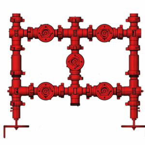
3″ FIG. 1502 – 5 VALVES, 2 CHOKE MANIFOLD
Navigate the most demanding oilfield environments with confidence using the 3″ FIG. 1502 – 5 Valves, 2 Choke Manifold, supplied by Blaze Sales and Service. Engineered for unparalleled safety and precise control in high-pressure applications, this robust manifold system is the cornerstone of efficient well testing, flowback, and production operations. Its heavy-duty construction and advanced valve configuration ensure reliable performance and a significant reduction in operational downtime, safeguarding your most critical assets.
CONSTRUCTION:
- 3″ Fig. 1502 Choke Manifold Assembly.
- Consists of two numbers of choke and five numbers of plug valve.
- Provision for measurement of pressure and temperature.
- Available with skid.
- Approximate weight is 828 kg.
Features:
- Robust FIG. 1502 Connections: Designed to withstand extreme pressures up to 15,000 PSI CWP (Cold Working Pressure), ensuring secure and leak-free connections critical for high-pressure oilfield operations.
- Five High-Performance Valves: Equipped with five strategically placed valves, offering comprehensive control over fluid pathways, isolation, and diversion, enhancing operational flexibility and safety.
- Dual Choke Configuration: Features two integrated chokes (positive or adjustable options available), enabling precise control of flow rates, pressure reduction, and well optimization, crucial for managing diverse reservoir conditions.
- Heavy-Duty Forged Construction: Manufactured from premium, high-strength alloy steel, the manifold body is forged for superior integrity and durability, resisting erosion, corrosion, and fatigue in aggressive environments.
- Optimized Flow Dynamics: Engineered internally to minimize turbulence and pressure drops, promoting efficient fluid handling and extending the lifespan of the manifold and associated equipment.
- Enhanced Safety Protocols: Designed with multiple layers of safety features, including redundant sealing mechanisms and robust locking systems on valves and chokes, to prevent accidental operations and ensure operator protection.
- Ease of Maintenance: Modular design facilitates straightforward inspection, repair, and replacement of components, reducing maintenance time and operational costs.
- Sour Service Capability (Optional): Available with configurations compliant with NACE MR0175/ISO 15156 for resistance to sulfide stress cracking, suitable for sour gas applications.
Specifications and Technical Details:
- Nominal Size: 3 inches
- Pressure Rating: FIG. 1502 (15,000 PSI CWP – Cold Working Pressure)
- Number of Valves: 5
- Number of Chokes: 2 (configurable as positive, adjustable, or a combination)
- End Connections: FIG. 1502 hammer unions
- Material: High-strength alloy steel, typically AISI 4130 or equivalent, heat-treated for optimal mechanical properties. (Specific material grades available upon request).
- Operating Temperature Range: Typically -20°F to +250°F (-29°C to +121°C), extended ranges available for specific applications.
- Service Compatibility: Standard service for oil, gas, and drilling fluids; Sour Service (NACE MR0175/ISO 15156) compliant options available.
- Hydrostatic Test Pressure: 22,500 PSI (1.5 times CWP)
- Working Medium: Oil, natural gas, drilling fluid, water, and other well fluids.
- Manufacturing Standards: API 6A, API Spec 16C, and other relevant industry standards (e.g., ASME, ISO) as applicable.
Application:
The 3″ FIG. 1502 – 5 Valves, 2 Choke Manifold is an indispensable component in a wide array of high-pressure oilfield operations, including but not limited to:
- Well Testing and Clean-up: Precisely managing flow from newly drilled or stimulated wells to evaluate reservoir performance and remove completion fluids.
- Flowback Operations: Controlling and diverting flow during the initial phase of well production after hydraulic fracturing or stimulation.
- Production Manifolds: Serving as a critical interface for directing and regulating the flow of hydrocarbons from multiple wells into processing facilities.
- Kill and Choke Manifolds: Integral to well control operations, providing a means to circulate out kicks and manage wellbore pressure.
- Frac Stack Components: Utilized as a vital part of the surface equipment during hydraulic fracturing to manage fluid flow and pressure.
- High-Pressure Diversion: Facilitating safe and efficient diversion of high-pressure fluids during various well interventions and operations.
For reliable, high-performance oilfield equipment, trust the expertise of Blaze Sales and Service.
Contact: Call +1 405 666 5011
E-mail at seo@blazess.com
Additional information
Weight | 1821.6 lbs |
---|---|
Dimensions | 75.5 × 64.8 × 14 in |
There are no reviews yet.